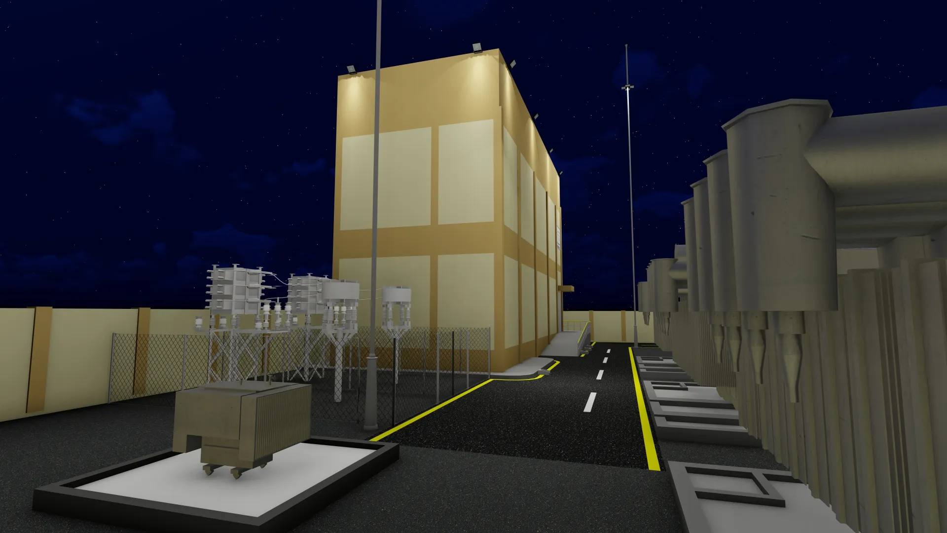
Global Solar-Storage Surge Signals Substation Transformation
Australia's National Electricity Market connection pipeline has jumped 43% to 80.9 GW, driven almost entirely by solar and battery storage projects that now exceed the grid's existing 77 GW of capacity. This milestone, reported in October 2026, is not an isolated event. From India's 350 GW solar target to Masdar's NZ$1 billion renewables-plus-storage push in New Zealand, the pattern is clear: variable generation and grid-scale batteries are becoming the default new capacity worldwide. For project owners and engineers in Jordan, Saudi Arabia and the wider GCC, the message is direct — electrical substation design renewable integration must move from a niche consideration to the standard design basis for every new and upgraded substation.
Why Substation Architecture Must Evolve
From Passive Nodes to Active Grid Assets
Traditional substations were designed as passive voltage transformation points: receive power at transmission level, step down, distribute. Today's renewable-rich grids demand substations that actively manage two-way power flows, fast frequency response, and voltage support from inverter-based resources (IBR). A 380/132 kV bulk supply point or a 132/33 kV distribution substation now routinely hosts:
- Utility-scale solar PV or wind farm connections at medium or high voltage
- Battery energy storage systems (BESS) providing firm capacity and ancillary services
- Grid-forming inverters that synthesize inertia and voltage waveforms
- Dynamic reactive compensation (STATCOM, SVC) for voltage stability
Each addition changes the primary engineering (busbar layout, breaker ratings, fault levels) and the secondary engineering (protection philosophy, SCADA/IEC 61850 data models, communication redundancy). HREO's portfolio of 380/132 kV BSP designs and 110/33 kV substations in Makkah already reflects this shift toward multi-functional substation architectures.
Battery Storage Integration: Primary and Secondary Design Impacts
Primary Engineering Considerations
Connecting BESS at the substation busbar introduces new fault-current contributions, harmonic spectra, and charging/discharging duty cycles. Key design adjustments include:
- Short-circuit studies that model inverter fault current (typically 1.1–1.5 p.u.) alongside synchronous machine contributions
- Breaker and switchgear ratings verified for DC component and high X/R ratios from power electronics
- Busbar and conductor thermal ratings assessed for rapid charge/discharge ramps
- Earthing and bonding designs that address both AC and DC fault paths
- Fire suppression and containment for lithium-ion enclosures per NFPA 855 and local civil defence codes
Protection, Control and IEC 61850
On the secondary side, the protection scheme must discriminate between inverter fault signatures and conventional faults. Adaptive protection settings, wide-area monitoring, and IEC 61850 GOOSE/Sampled Values become essential. HREO's utility network design service covers primary and secondary engineering for substations up to 380 kV, including protection coordination studies aligned with SEC and IEC standards.
Grid-Forming Inverters and the Inertia Gap
Australia's market operator now seeks system-security contracts for grid-forming BESS after completing technical trials. The GCC faces a parallel challenge: as synchronous generators retire or operate at minimum load, synthetic inertia from grid-forming inverters must fill the gap. Substation design must therefore accommodate:
- Dedicated bays for grid-forming BESS with fast frequency response (FFR) capability
- High-speed communication (sub-4 ms GOOSE) between inverter controllers and substation protection relays
- Time-synchronization (IEEE 1588/PTP) across the substation LAN for phasor measurement units (PMU) and traveling-wave fault locators
- Cybersecurity zoning per IEC 62443 and national regulations (e.g., Saudi NCA/SEC OT security guidelines)
These requirements influence control building layout, cable routing, and the BIM coordination of MEP, structural and electrical disciplines at LOD 400/500.
Transmission Planning Alignment: Lessons from India and Australia
India's experience — highlighted by Hartek Power's CEO — shows that battery storage deployment without coordinated transmission expansion leads to renewable curtailment. Australia's 80.9 GW pipeline faces similar congestion risks. The GCC equivalent is the massive grid reinforcement under Saudi Vision 2030, NEOM's 100% renewable grid, and Jordan's 2030 renewable targets. Practical steps for substation owners:
- Commission joint generation-transmission studies before finalizing BESS siting and capacity
- Design substation bays and land reserves for future transmission upgrades (e.g., 380 kV extension from a 132 kV switching station)
- Adopt modular GIS or hybrid switchgear to allow bay additions without full rebuilds
- Use construction supervision and project management to ensure long-lead equipment (power transformers, GIS, protection panels) aligns with the transmission schedule
GCC-Specific Drivers: Vision 2030, NEOM and Regional Interconnection
Saudi Arabia's target of 58.7 GW renewable capacity by 2030, the GCCIA interconnection upgrades, and NEOM's fully renewable microgrid create a concentrated demand for advanced substation engineering. HREO's Saudi entity, High Rock Consultant Engineers, has delivered substation designs for NEOM (NIC Circle 380/132 kV BSP), ROSHN developments, and the Holy Sites (Arafat Central 110/33/13.8 kV). These projects integrate:
- Multi-voltage busbars (380/132/13.8 kV) for flexible generation and load connection
- Gas-insulated switchgear (GIS) for compact urban and holy-site footprints
- Redundant IEC 61850 process bus architecture
- Civil-structural designs for seismic Zone 3 and harsh environmental conditions
In Jordan, the Ministry of Energy's renewable roadmap and grid code updates require similar substation upgrades for solar PV and wind farm interconnections. Egypt's 2035 integrated energy strategy adds further regional demand.
Comparing Substation Technology Options for Renewable Integration
| Technology | Typical Voltage | Footprint | Renewable/BESS Suitability | Lead Time |
|---|---|---|---|---|
| Conventional AIS | Up to 380 kV | Large | Standard solar/wind; limited BESS bays | 12–18 months |
| GIS (Gas Insulated Switchgear) | 132–380 kV | Compact (30–50% of AIS) | High — ideal for urban, holy sites, BESS integration | 14–20 months |
| Hybrid (AIS bus + GIS bays) | 132–230 kV | Medium | Good — phased expansion friendly | 10–16 months |
| Modular/Prefabricated E-House | Up to 33 kV (MV) | Minimal | Excellent for distributed solar/BESS | 6–10 months |
Selection depends on land availability, expansion plans, environmental constraints, and program. HREO's multidisciplinary team evaluates these trade-offs during concept and FEED stages.
Key Takeaways
- Solar-plus-storage is now the dominant new-capacity archetype globally; substation design must treat renewable integration as the baseline, not an add-on.
- Primary engineering (busbar, switchgear, earthing) and secondary engineering (IEC 61850, adaptive protection, cybersecurity) are equally critical for BESS and grid-forming inverter integration.
- Transmission-generation coordination studies prevent curtailment and stranded assets — engage them early in the project development cycle.
- GIS and hybrid switchgear offer the compactness and modularity needed for GCC urban and giga-project sites.
- BIM-driven coordination at LOD 400/500 across civil, structural, MEP and electrical disciplines reduces clashes and accelerates delivery of complex multi-voltage substations.
How HREO Can Help
HREO delivers end-to-end electrical substation design — civil, structural, primary and secondary engineering — for voltages up to 380 kV, including GIS substations, OHTL/UGC connections, and renewable/BESS integration. Our BIM department produces coordinated LOD 400/500 models on Autodesk Construction Cloud, and our supervision team oversees construction to IEC/SEC standards. Recent references include the NEOM NIC Circle 380/132 kV BSP and the Arafat Central 110/33/13.8 kV substation. Contact us via our contact page to discuss your substation or grid integration project.
Conclusion
The global pipeline data confirms that the energy transition is a substation transition. Every new solar farm, wind park, or battery project lands at a substation that must handle bidirectional flows, fast frequency response, and digital communication natively. For Jordan, KSA and the GCC, the opportunity is to standardize these capabilities now — using proven IEC 61850 architectures, GIS technology, and BIM-enabled delivery — so that the next 50 GW of renewable capacity connects reliably, securely, and on schedule.
Frequently asked questions
What voltage levels does HREO design substations for?
HREO designs substations up to 380 kV, including 380/132 kV bulk supply points, 132/33 kV, 110/33 kV, 110/13.8 kV, and lower voltage distribution substations, with GIS and AIS technologies.
How does IEC 61850 benefit renewable-integrated substations?
IEC 61850 provides standardized object models, GOOSE for fast tripping/interlocking, Sampled Values for process bus, and time synchronization — essential for coordinating inverter-based resources, BESS, and wide-area protection schemes.
What is the typical lead time for a 380 kV GIS substation?
A 380 kV GIS substation typically requires 14–20 months for equipment procurement and delivery, depending on manufacturer capacity and project specifications. Early ordering of long-lead items (power transformers, GIS bays) is critical.
Can HREO provide BIM models for substation projects at LOD 500?
Yes. HREO's BIM department delivers coordinated multi-discipline models at LOD 100–500 following ISO 19650 on Autodesk Construction Cloud, including as-built LOD 500 models for substation projects.
Does HREO design overhead transmission lines and underground cables for substation connections?
Yes. HREO provides OHTL engineering up to 500 kV (route plans, sag/tension, stringing charts, tower grounding) and UGC engineering (cable routing, sheath bonding, terminations) as part of complete substation connection packages.
References (5)
- Solar and battery storage push Australia's NEM connection pipeline up 43% to 80.9GW
- India must align battery storage and transmission to cut renewable curtailment
- India's installed solar PV capacity to exceed 350 GW by 2030, says IEA
- Masdar explores NZ$1 billion solar PV, wind and storage investment in New Zealand
- Grid-forming battery storage trials completed in Australia