
Across the architecture, engineering, and construction (AEC) sectors in Saudi Arabia, Jordan, and the wider GCC, managing project complexity requires rigorous data integration rather than fragmented documentation. Implementing disciplined BIM coordination and clash detection processes has become critical to resolving discrepancies before construction starts on site. Recent industry research highlighting communication gaps between traditional 2D drafting and multidimensional models underscores how disconnected workflows escalate rework, inflate contingency budgets, and compromise delivery schedules.
Context and Industry Background: The Communication Disconnect
In modern capital projects, delivery teams frequently face a persistent bottleneck: while design intent is generated using parametric authoring tools such as Autodesk Revit, site teams and specialty subcontractors often rely on flat 2D deliverables or static PDF submittals. According to recent technical findings released by Graphisoft regarding communication fragmentation in AEC projects, failure to integrate project management systems with model authoring platforms remains a leading cause of change orders and scheduling disputes.
When design teams operate in disciplinary silos—architectural, structural, mechanical, electrical, and plumbing—unresolved geometric and spatial interfaces accumulate silently. In fast-track developments, discovering these conflicts in the field can delay testing and commissioning by weeks. Bridging this disconnect requires an institutional commitment to international standards, specifically the ISO 19650 series, where a Common Data Environment (CDE) links project controls with living digital models.
The Core Challenge: Managing Multidisciplinary Congestion
The primary challenge in dense institutional, commercial, and technical facilities is spatial congestion within ceiling plenums, vertical service shafts, and structural penetrations. Without active coordination, three distinct categories of clashes threaten construction progress:
- Hard Clashes: Physical intersections where two components occupy the same physical space, such as an HVAC supply duct piercing a post-tensioned beam or high-voltage cable trays clashing with gravity drainage lines.
- Soft Clashes (Clearance Conflicts): Violations of operational, maintenance, or safety buffers around equipment, such as insufficient access clearance around air handling unit (AHU) motor compartments or transformer maintenance zones.
- Workflow / 4D Sequencing Clashes: Scheduling contradictions where the installation order creates logistical impossibilities, such as sealing a plant room before lowering heavy centrifugal chillers onto their inertia pads.
Traditional drawing review methods catch fewer than 20% of spatial clearances in dense service zones. Addressing these issues demands a structured, step-by-step resolution process anchored in objective engineering validation.
Step-by-Step Approach: Implementing a Validated Coordination Workflow
To prevent design errors from migrating to site operations, engineering teams must execute a methodical resolution cycle. The following four-stage approach reflects industry best practice under ISO 19650 information management principles.
Step 1: Information Structuring and Model Health Auditing
Before initiating automated clash tests, the federated model must be sanitized. Each disciplinary model (Architectural, Structural, MEP) is audited for origin alignment, shared coordinate systems, and parameter consistency. Native authoring files from software like Revit are exported to open standards, specifically openBIM Industry Foundation Classes (IFC) or native NWC files for clash analysis. Drawing lines disguised as model elements are flagged, and element families must reflect true equipment dimensions.
Step 2: Matrix-Driven Conflict Rules and False-Positive Filtering
Running unconstrained clash tests in Navisworks Manage or cloud-based coordination platforms often generates thousands of meaningless data points. Effective teams deploy a disciplined Clash Matrix that isolates critical systems into prioritized tests. Tolerances are defined based on project stage and constructability thresholds:
| Clash Test Priority | Primary Subsystem | Conflicting Subsystem | Applied Tolerance (mm) | Resolution Objective |
|---|---|---|---|---|
| Level 1 (Critical) | Primary Structural Frames (Beams/Columns) | Gravity Drainage & Major HVAC Ductwork | 0.00 mm (Zero Tolerance) | Preserve structural integrity; eliminate sleeve core-drilling. |
| Level 2 (High) | Pressure Pipework & Cable Trays | HVAC Ductwork & Secondary Framing | 25.00 mm | Maintain designated routing corridors and branch take-offs. |
| Level 3 (Medium) | MEP Terminal Units / Light Fixtures | Ceiling Grids & Architectural Bulkheads | 10.00 mm | Ensure architectural alignment and aesthetic compliance. |
| Level 4 (Clearance) | Terminal VAVs, Valves, Switchgear | Adjacent Walls & Access Panels | 500.00 mm buffer | Ensure statutory maintenance clearances and egress corridors. |
Step 3: Issue Tracking, BCF Communication, and Design Workshops
Detected conflicts are grouped by zone, system, and severity rather than reviewed individually. Utilizing BIM Collaboration Format (BCF) workflows within platforms like Autodesk Construction Cloud (ACC), coordination issues are assigned directly to discipline leads with defined resolution deadlines. Weekly interdisciplinary coordination meetings focus exclusively on unresolved Level 1 and Level 2 issues, eliminating the ambiguity of informal markups.
Step 4: Sign-Off and Extraction of Constructible Shop Drawings
Once spatial conflicts in a designated sector reach approved status, the coordinated geometry is frozen. Constructible shop drawings and Bar Bending Schedules (BBS) are extracted directly from the Level of Development (LOD) 400 models. Because geometry is verified in three dimensions, fabricators proceed with off-site prefabrication with high spatial confidence.
Results and Measurable Impact Reported by Industry Studies
Field studies evaluating projects that integrated automated clash coordination workflows with project management platforms document significant quantitative benefits:
- Reduction in Site RFIs: Constructability-related Requests for Information dropped by 45% to 65% compared to conventional 2D CAD project baselines.
- Mitigation of On-Site Rework: Direct field rework caused by service conflicts fell to under 1.5% of total mechanical and electrical contract value.
- Schedule Certainty: Project commissioning phases advanced without spatial hold-ups, preventing cascade delays in final authority approvals.
- Supply Chain Acceleration: Off-site spooling of ductwork and piping runs increased by over 30%, optimizing labor efficiency on congested job sites.
Key Lessons Learned for AEC Stakeholders
Deploying digital coordination tools requires strategic governance to deliver tangible return on investment. The following principles represent critical takeaways for developers, main contractors, and lead consultants:
- Engage BIM Teams Early: Involving coordination specialists during concept and detailed design prevents costly rework, whereas late deployment during construction acts merely as damage control.
- Enforce True Manufacturer Dimensions: Utilizing generic equipment models creates a false sense of security; parametric families must reflect true physical clearance requirements.
- Treat the Model as the Single Source of Truth: Never permit site adjustments to override model coordination without feeding field updates back into as-built records.
- Standardize via ISO 19650: Clear naming conventions, status codes, and common data protocols are vital to prevent version confusion among distributed teams.
Key Takeaways
- Model coordination is a predictive risk management discipline, not merely a 3D visualization exercise.
- A defined Clash Matrix prevents team fatigue by filtering out insignificant clashes and focusing on structural and MEP integrity.
- Integrating cloud-based issue tracking platforms bridges the historical gap between project managers and engineering modelers.
- LOD 400 fabrication modeling enables off-site manufacturing and protects project budgets from expensive site re-engineering.
How HREO Can Help
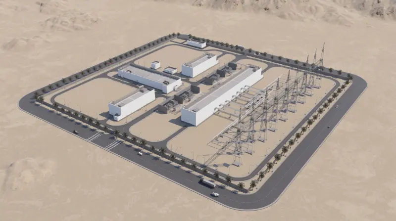
Holy Rock Consultant Engineers (HREO) delivers comprehensive engineering and digital delivery support across Jordan, Egypt, and Saudi Arabia—where it operates as High Rock Consultant Engineers. Backed by 36+ years of multidisciplinary expertise, an ISO 9001:2015 certified quality framework, and an Autodesk-certified team, HREO provides advanced BIM services from LOD 100 through LOD 500. Through established expertise executing complex projects such as the Royal Commission for AlUla Headquarter Office & Business Park Project and high-precision infrastructure such as the NIC Circle 380/132 kV Electrical Substation, HREO targets zero-clash coordination across structural, architectural, and MEP disciplines. Discover how our integrated solutions streamline project delivery by visiting our engineering services portfolio or reaching out via our contact us page.
As digital project delivery matures across the Middle East, structured coordination remains the cornerstone of buildability. By aligning design teams, construction managers, and digital workflows within a unified framework, engineering leaders ensure that complex investments move from parametric design to physical realization safely, efficiently, and on schedule.
Frequently asked questions
What is the difference between hard clashes and soft clashes in BIM coordination?
A hard clash occurs when two components physically occupy the same coordinate space, such as a pipe passing through a structural beam. A soft clash, or clearance conflict, occurs when an element violates required operational, buffer, insulation, or maintenance clearances without physical contact.
How does ISO 19650 improve BIM clash detection workflows?
ISO 19650 provides standardized protocols for information management and status codes within a Common Data Environment (CDE). This ensures that engineering disciplines coordinate against verified, single-source models, preventing conflicting revisions and unstructured communication.
Why is an automated Clash Matrix necessary in multidisciplinary BIM projects?
An automated Clash Matrix defines precise cross-disciplinary clash tests and clearance tolerances. By filtering out irrelevant contact points and cosmetic clashes, it allows the engineering team to focus on critical constructability hazards like structural penetrations and major MEP routing.